


Fiber optic networks offer advantages such as high transmission bandwidth, low latency, and strong immunity to electromagnetic interference. However, during actual deployment and operation, links may still experience connection failures, unstable operation, or degraded transmission performance. Numerous field cases show that most faults do not originate from the fiber itself, but are jointly caused by connector contamination, improper installation practices, mismatched parameter configurations, and mechanical stress.
Establishing a systematic fault analysis approach not only improves maintenance efficiency, but also reduces repeated troubleshooting and ensures long-term stable operation of fiber optic networks.
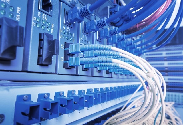
Different types of fiber optic faults manifest in clearly different ways. Based on actual operating status, they can be roughly divided into the following categories.
Failure to establish a link is a relatively obvious fault type. After connection, the device port cannot recognize the optical signal, the link indicator stays off, and services cannot communicate normally.
Such problems usually have the following characteristics:
The main causes of failure to establish a link include:
Because such faults have obvious characteristics, they can usually be quickly located through physical connection inspection.
Compared with complete link disconnection, intermittent faults are more hidden and are among the more difficult problems in network maintenance.
The link can be established normally, but during operation the following may occur:
The causes of such problems are mostly concentrated at the physical layer, including:
Because the link is not completely interrupted, relying only on device logs is often insufficient for accurate diagnosis, and comprehensive analysis combined with on-site testing is needed.
Some fiber optic links can remain online, but actual communication quality is significantly degraded.
Common symptoms include:
Causes of performance degradation usually include:
Such problems do not immediately cause link interruption, but gradually compress system operating margins and increase the probability of subsequent faults.
Fiber optic connector end faces are extremely sensitive to contamination. Dust, oil, moisture, and tiny particles in the air can attach to the end face, affecting optical signal transmission.
Contamination usually brings the following changes:
Because the fiber core diameter is extremely small, even particles imperceptible to the naked eye can have a significant impact on optical transmission. Therefore, end-face cleanliness has always been an important factor affecting link quality.
Standardized installation practices are directly related to the long-term stable operation of fiber optic systems.
Common non-standard operations during construction include:
These problems may not immediately manifest as faults during initial installation, but as operating time increases, mechanical stress gradually affects the internal transmission performance of the fiber, ultimately causing link stability to decline.
Therefore, installation quality not only affects current operating status, but also determines the lifecycle of the entire network.
Fiber optic systems have an end-to-end transmission structure, and all components must remain fully matched.
If the following parameters differ, normal link operation may be affected:
Any inconsistency in a key parameter can prevent the link from being established or reduce operating stability.
Therefore, confirming parameter consistency before device deployment is more efficient than troubleshooting later.
A scientific troubleshooting process can significantly shorten fault location time and reduce maintenance costs.
Step 1: Check Physical Connection Status
Fault diagnosis should begin at the physical layer.
Key inspection items include:
Professional testing tools should then be used to inspect the connector end faces.
If contamination is found, clean the end faces, reconnect, and observe link status changes.
Field maintenance experience shows that a considerable number of link faults can be restored simply by cleaning the end faces.
Step 2: Confirm Link Parameter Consistency
After completing physical inspection, the entire link configuration should be further verified.
Main check items include:
By verifying item by item, compatibility problems caused by configuration inconsistencies can be ruled out.
Step 3: Test Optical Link Performance
When a link can be established but operates unstably, optical performance should be further evaluated.
Key test indicators include:
If the received optical power stays close to the minimum receive sensitivity of the module for a long time, the link becomes susceptible to environmental changes, leading to higher bit error rates or service fluctuations.
Therefore, link quality should be judged by combining theoretical budget and actual measurement results.
During the network construction stage, reasonable choices should be made based on application needs:
Keeping all components consistent can effectively reduce link loss and improve system compatibility.
Before engineering implementation, complete link planning should be completed, including:
Adequate upfront design can reduce on-site adjustments and improve overall deployment efficiency.
Construction quality should be strictly controlled during installation.
Key points include:
Standardized construction can reduce mechanical damage and improve long-term link stability.
For installation environments with high mechanical stress, fiber cable protection measures should also be strengthened to reduce the risk of loss during long-term operation.
The maintenance stage should form standardized management processes.
Main measures include:
For high-density patching environments with frequent connector insertion and removal, inspection frequency should be increased to reduce the impact of contamination accumulation and end-face wear.
Continuous maintenance management can effectively extend the service life of fiber optic links and reduce fault rates.
Although fiber optic connection faults manifest in various ways, most problems concentrate on basic aspects such as physical connections, installation practices, parameter matching, and routine maintenance. Establishing a layered diagnostic process from physical inspection and parameter verification to optical performance testing helps quickly identify the root cause of faults and improves maintenance efficiency.
Compared with passive handling after faults occur, establishing a standardized management system during network planning, equipment selection, construction and installation, and operation and maintenance can better improve the stability and reliability of fiber optic links, reduce performance fluctuations and O&M costs, and provide solid support for long-term stable network operation.
Copyright © 2023-2025 APAC Cable (Guangzhou) Co., Ltd. All Rights Reserved 粤ICP备2025482347号-1
Address: No.361, Xintang Avenue West, Xintang Town, Zengcheng District, Guangzhou, China





 粤公网安备44011802001235号